


Go-Kart Project
During the summer of 2020, amidst the Covid-19 pandemic, my brother and I embarked on a project to fully design and build a go-kart from scratch. With limited opportunities for hands-on learning at the time, we saw this as a perfect way to develop my engineering skills before entering college. We started by designing the go-kart frame in SolidWorks, carefully considering dimensions and structural integrity. To keep things simple and accessible, we decided to construct the frame out of wood. For the power source, we used a PREDATOR 6.5 HP lawn mower engine and researched all the necessary components, including the clutch, chain, sprocket, axle, motor mount, and wheels.
One of the biggest challenges we faced during assembly was an unexpected issue with the axle and hub fitment. We had purchased a 1-inch axle and a 1-inch hub to attach the sprocket, but when we tried to slide the hub onto the axle, the fit was too tight. Drawing on the principle of thermal expansion, we devised a solution: we heated the hub over a bed of hot coals to expand it slightly, allowing us to carefully slide it into position. Since we only had one opportunity to fit the hub before it cooled and contracted, we measured twice and acted once, ensuring everything was perfectly aligned before proceeding.
As seen in the images on the right, our initial design featured four wheels, but we quickly realized that the steering system lacked structural integrity and did not allow for sharp turns. After some use, the steering mechanism failed, and we needed to go back to the drawing board. Our options were to either reinforce the frame with stronger materials or completely redesign the front end. Ultimately, we took a creative approach, cutting the front of a salvaged kids’ bike and attaching it to the frame to convert the kart into a tricycle-style design. This modification significantly improved the handling and stability of the go-kart.
This project was an incredible learning experience, allowing me to develop practical problem solving skills and reinforce my passion for engineering and hands-on building. From designing in CAD to troubleshooting mechanical challenges, this project sparked my interest in mechanical engineering and gave me a strong foundation in creativity, critical thinking, and perseverance.

Test Drive of the Final Go-Kart Design
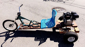
Final Go-Kart Design
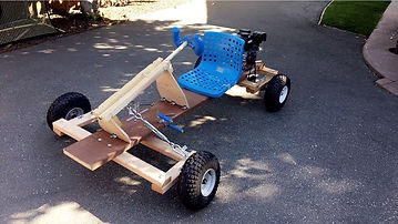
Initial Go-Kart Design
Riverhawk Racing (FSAE)
In the fall of 2022, I joined my university’s Formula SAE (FSAE) team, Riverhawk Racing, as part of the bodywork team, focusing on designing the car’s body panels. One of my main projects was developing an undertray, a crucial aerodynamic component designed to speed up airflow beneath the car, creating a low-pressure region to increase downforce and reduce drag. This was my first exposure to Computational Fluid Dynamics (CFD), and I had the opportunity to not only contribute to the design process but also learn how to analyze and optimize aerodynamic performance through simulation. After several iterations using SolidWorks CFD, our final design resulted in a drag coefficient of 0.4256 and generated 332 lbs of downforce at 35 mph, significantly improving the car's overall aerodynamics.
To develop the undertray, I worked extensively in SolidWorks, helping to design and refine the diffuser at the rear of the car. Our goal was to maximize the aerodynamic efficiency of the undertray while ensuring it was manufacturable within our team’s capabilities. Using SolidWorks CFD, we iterated on our design, analyzing airflow behavior and adjusting key parameters to achieve optimal results.
Once we finalized the design, we moved on to manufacturing. Our process involved traditional fiberglass fabrication methods. We started by cutting layers of 2-inch thick pink insulation foam by hand to form the rough shape of the undertray. These layers were glued together and further refined using a robotic arm from our university's plastics department, which allowed us to create a more precise mold. To ensure easy removal of the final fiberglass part, we wrapped the foam mold in plastic film. The next step involved soaking fiberglass sheets in resin and carefully laying them over the foam mold. Once the fiberglass had fully cured, the hardened panel was removed from the foam, producing a lightweight yet strong aerodynamic component ready for installation on the car.
This experience was a valuable introduction to aerodynamics, CFD, and composite manufacturing. Not only did I improve my CAD modeling and simulation skills, but I also gained hands-on experience with fabrication techniques, reinforcing my passion for engineering and problem solving in motorsports applications.
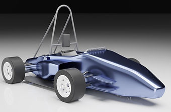
FSAE Car Design

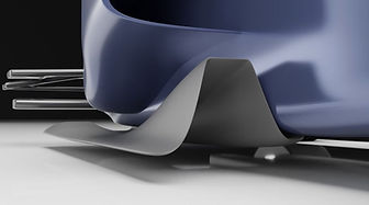
Undertray Design

Fiberglass Parts
Foam Mold

CFD Simulation

CFD Simulation
"B737" Wing Loading Analysis
For my Finite Element Analysis (FEA) final project, my team and I conducted an in-depth study of the forces acting on a “Boeing 737” wing. The goal of this project was to use FEA to analyze how aerodynamic and structural loads impact the wing's integrity. We examined key forces such as lift, drag, and the engine's weight while using a composite material selected from the AGATE (Advanced General Aviation Transport Experiments) database, which is commonly used in aerospace applications. Understanding how these forces interact with the wing's structure is crucial for ensuring safety and performance in the aviation industry.
Our methodology involved using two powerful simulation tools: ANSYS Fluent for computational fluid dynamics (CFD) analysis and Abaqus for structural analysis. We started by creating a swept-back wing model using a NACA 2414 airfoil and incorporated spars and ribs to enhance structural integrity. The wing was then meshed with careful attention to element distribution, ensuring finer mesh elements in areas of higher stress concentration. For material selection, we chose TORAY T700SC-12K-50C/#2510 Plain Weave Fabric, a high-performance composite known for its strength and durability. The applied loads included a lift force of approximately 151,220 N, a drag force of 6,360 N, and an engine weight of 23,242 N, each strategically applied to simulate real-world conditions.
Analyzing the results, we observed how the wing deformed under these loading conditions and assessed the distribution of stress across its structure. The FEA simulations provided valuable insights into potential failure points on the wing. One of the main challenges we encountered was the complexity of modeling the wing accurately. While we did our best to create a realistic design, future improvements could include incorporating multiple airfoil sections, additional spars and ribs, and a more refined swept-back shape. Additionally, a more systematic application of the engine weight and drag forces would improve the accuracy of the simulation. Despite these challenges, this project was a great learning experience, reinforcing my understanding of structural and aerodynamic analysis in aerospace engineering.

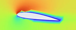
CFD of NACA 2414 Airfoil
Wing Model

Wing Deflection
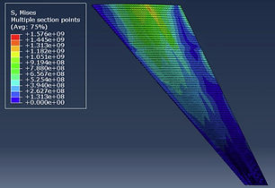
FEA Stress

TORAY T700SC Plain Weave Fabric
Car Door Mechanism
During my time at Alef Aeronautics, I was given the responsibility of designing and developing the butterfly door mechanism for the prototype vehicle. This was a crucial task as the doors had to function seamlessly while maintaining the vehicle’s aerodynamic design. My first challenge was to modify the existing CAD model of the car frame to create space for the door hinge and arms. This required careful adjustments to ensure structural integrity while integrating the door mechanism smoothly into the design. Once the necessary modifications were made, I began designing the actual components in SolidWorks.
Precision was critical in this process. I had to maintain proper dimensions that aligned with the airfoil shape of both the body and the doors, ensuring a smooth aerodynamic profile. Additionally, I needed to carefully design clearances to prevent interference between the door and the frame when opening. After finalizing the initial design, I moved on to rapid prototyping. Using a 3D printer with carbon fiber-infused PETG, I created multiple iterations of the parts, allowing me to test and refine the mechanism efficiently.
To properly test the door mechanism before the actual doors were fabricated, I CNC-machined MDF panels to simulate the shape of the real carbon fiber doors. While MDF is significantly heavier than carbon fiber, this ensured that if the mechanism worked under these conditions, it would be structurally sound for the final product. After multiple rounds of testing, I identified a key issue; while carbon fiber-infused PETG was suitable for early prototypes, it lacked the strength necessary for long-term use. To solve this, I outsourced the manufacturing of the critical load-bearing components in aluminum. I created detailed 2D engineering drawings and provided manufacturers with precise CAD models to ensure accurate fabrication.
Another essential aspect of the design was selecting the appropriate gas spring to assist with door operation. I conducted extensive research to determine the optimal force and length needed to balance the door’s movement. The gas spring had to be carefully positioned to ensure that it would hold the door open when needed while also acting as a controlled closing mechanism. This project provided me with valuable hands-on experience in mechanical design, prototyping, material selection, and real-world problem solving in a fast-paced startup environment.
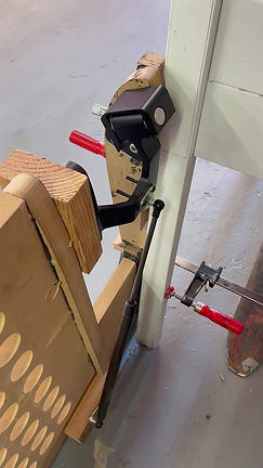
Car Door Mechanism Motion Analysis


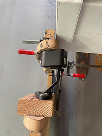
Car Door Mechanism Multiple Views
Learning-Based Wind-Aware Planner for Drone Bridge Inspections
For my master's capstone project at UC Berkeley, I am working on developing a learning-based wind-aware planner for drone bridge inspections. The goal of this project is to enhance precise path tracking, improve the energy efficiency of the drone, and reduce the risk of obstacle collisions by training a machine learning algorithm to estimate local wind velocities. The algorithm utilizes data from the drone’s inertial measurement unit (IMU), motor speeds, and camera to predict wind conditions in real time. With this information, our path planning algorithm can adapt to wind disturbances and improve the drone's overall performance in complex environments.
My primary responsibility in this project has been to generate a large dataset of wind conditions to train our machine learning algorithm. To accomplish this, I developed a Python script to automate the creation of diverse environments for computational fluid dynamics (CFD) simulations. While our final goal is to model wind and turbulence in a bridge environment, we began by using simplified geometries such as cubes and cylinders to streamline the initial testing process. Once the script generates a wide range of CAD files, I automated the process of running CFD simulations in ANSYS Fluent. This automation includes importing the geometries, defining boundary conditions such as inlet and outlet airflow, and iterating through various inlet velocities.
From each CFD simulation, I was able to extract approximately two million data points, providing wind velocity information in the x, y, and z directions at each point in the environment. The next phase of my work involved integrating this wind data into a drone simulation platform called AirSim. In this environment, we programmed the drone to follow a predefined flight path through the turbulent wind conditions. During these flights, we collected IMU and motor speed data, which is then used to train our machine learning algorithm to predict wind conditions based on onboard sensor inputs.
Looking ahead, we aim to incorporate camera data into our wind estimation process. By extracting object distances and dimensions from the drone’s camera feed, we can refine our wind predictions and improve the algorithm’s accuracy in real-world scenarios. Once we achieve a reliable wind estimation model, we will integrate it into our bridge inspection planner, enabling safer and more precise drone navigation for structural inspections.
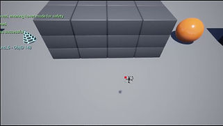
AirSim Drone Flight Simulation
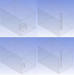
CAD Environment Generation

ANSYS Fluent CFD Simulation

Dimension Data from Camera

LSTM Results